
Understanding Fluid Flow and Heat Transfer Paths in Plate Heat Exchangers
Plate heat exchangers (PHEs) are often discussed primarily in terms of thermal performance—approach temperatures, heat transfer coefficients, and duty requirements. But at their core, PHEs are also highly engineered flow devices. Understanding how fluids actually move through a PHE is fundamental to selecting the right configuration, predicting performance, and maintaining long-term reliability.
This article breaks down fluid flow in single-pass and multi-pass plate heat exchangers, explains how channel count and pass arrangement affect heat transfer, and highlights practical considerations for operation and cleaning.
Single-Pass Plate Heat Exchangers
If you temporarily set aside heat transfer, a plate heat exchanger can be understood as a piece of highly efficient plumbing.
In a single-pass PHE, the vertically aligned ports on the left and right sides of the frame act as inlet and outlet headers for the hot and cold fluids. These ports pass through the fixed frame plate and extend through every heat transfer plate until they terminate at the pressure plate. Functionally, they behave like fully flooded distribution pipes.

Once fluid enters the exchanger, it fills these distribution ports and is then evenly divided into the available flow channels created by the stacked plates. The complete flow path of a single molecule is as follows:
- The fluid enters horizontally through the inlet port
- Turns 90 degrees and flows vertically through a single channel
- Turns 90 degrees again and exits horizontally through the opposing port
- One fluid fills the channels from the bottom up, while the other fills from the top down. This arrangement creates true countercurrent flow within the plate pack—one of the key reasons PHEs are so thermally efficient.
Why a Single-Pass PHE Can Have Dozens—or Hundreds—of Channels
A common misconception is that “single pass” implies a small or low flow unit. While they are the simplest units, a single-pass PHE can contain anywhere from two to several hundred parallel flow channels, and flows from the single digit to several thousand gallons per minute.
- The reason lies in plate count:
- The minimum number of plates in a PHE is three
- The number of flow channels equals the number of plates minus one
- A single-pass unit always routes each fluid vertically across the plates once
The number of passes and the number of channels are independent design variables. A single-pass exchanger may have 2 channels or 200+ channels depending on capacity, pressure drop limits, and thermal duty.
What Determines the Required Number of Channels?
The required channel count is driven by a balance of thermal and hydraulic factors:
- Required heat duty and flow rates
- Plate geometry and chevron pattern
- Allowable pressure drop
- Fluid viscosity and density
- Desired turbulence level
Using the plumbing analogy, adding plates increases the effective flow area—similar to widening a pipe. This reduces the pressure drop but also lowers the velocity across the plates, which can reduce turbulence and heat-transfer efficiency.
Optimal PHE design carefully balances:
- Port velocity
- Channel velocity
- Pressure drop
- Heat transfer efficiency
- Capital cost
Why Alternating Hot and Cold Channels Improves Efficiency
In a simple tube-in-tube heat exchanger, all heat transfer occurs across the surface of the inner tube. To increase surface area, the tube must be made wider or longer, both of which have performance and practicality trade-offs. A plate heat exchanger takes a different approach. By alternating hot and cold flow channels between thin, corrugated plates, a PHE creates massive heat transfer surface area within a compact footprint. Each plate contributes a heat transfer area on both sides. The heat transfer surface area is extremely dense, dramatically increasing efficiency without increasing equipment size.
Multi-Pass and Multi-Section Plate Heat Exchangers
How Multi-Pass Designs Differ from Single-Pass Systems
In all PHEs, heat transfer occurs as fluids flow vertically past one another through alternating channels. The longer the fluids remain in thermal contact, the greater the achievable temperature change (ΔT).
In theory, a very tall plate could provide a large ΔT in a single pass. In practice, equipment height is limited by plant layouts, ceiling heights, and service access.
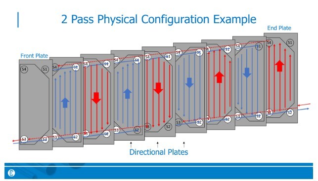
Multi-pass designs solve this constraint by routing fluid across the same plate height multiple times within a single exchanger. Instead of lengthening the plate, the effective heat transfer length is increased by adding passes.
Why Multi-Pass Units Require Ports on the Pressure Plate
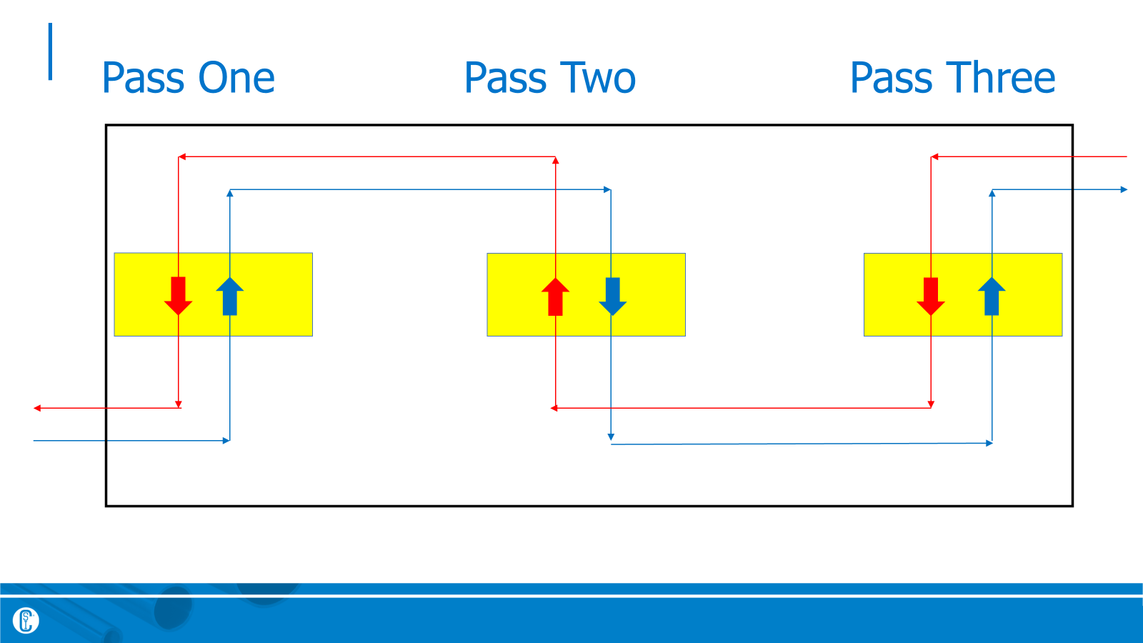
In a multi-pass exchanger, fluids must move from one pass group to the next in series. This requires fluid to enter on one side of the exchanger and exit on the opposite side.
To maintain true countercurrent flow, the hot and cold fluids must flow in opposite directions across each vertical pass throughout the heat exchanger. In a multiple pass configuration, this can only be achieved if the hot fluid enters the heat exchanger on the same frame end where the cold fluid exits.
This design ensures maximum thermal efficiency but introduces additional piping considerations during installation and maintenance.
Applications That Benefit from Multi-Pass Configurations
Single-pass PHEs are often limited to ΔT values around 30°F, which is sufficient for many HVAC and utility services.
However, hygienic and food-grade processes frequently require much higher temperature changes, such as:
- Pasteurization: 165°F → 36°F (ΔT = 129°F)
- Dairy processing: 170°F → 36°F (ΔT = 134°F)
- Brewing wort cooling: 210°F → 70°F (ΔT = 140°F)
Achieving these ΔTs in a reasonable footprint almost always requires multi-pass designs.
Performance and Maintenance Tradeoffs
Multi-pass exchangers introduce several operational considerations:- Higher pressure drop due to increased effective flow length
- Greater susceptibility to fouling in the first pass
- More complex cleaning requirements
- Additional piping removal required for plate access
In brewing applications, for example, the first pass often behaves like a filter, trapping organic material that bypasses upstream filtration. As fouling increases, heat transfer efficiency drops and pressure loss rises, requiring targeted CIP procedures or periodic plate inspection.
Single-pass units, by contrast, can often be configured with all connections on the fixed frame, allowing plate access without disturbing process piping.
How Engineers Determine the Optimal Number of Passes
Selecting the number of passes is an iterative engineering process. Engineers evaluate multiple configurations based on:
- Required heat duty
- Allowable pressure drop
- Fouling tendencies
- Cleaning constraints
- Installation limitations
- Total lifecycle cost
The final design presented is typically the lowest-cost solution that meets all thermal, hydraulic, and operational requirements.
Visualization and Practical Insights
Fluid Flow in PHEs: Misconceptions
One of the most common misunderstandings is the belief that fluids “snake” back and forth through a plate heat exchanger in series.
In reality:
- Fluids flow through many parallel channels per pass
- Each pass consists of multiple simultaneous flow paths
- Understanding this parallel nature is key to understanding plate configurations
Even experienced technicians may be able to disassemble and reassemble a unit without fully understanding the underlying flow logic—leading to persistent misconceptions.
Real-World Impact of Flow Path Design
Clogging and draining are two special considerations for multi-pass units. When organic material enters a multi-pass exchanger, the first pass can clog rapidly, requiring unique CIP strategies and periodic plate access. Multi-pass units have sections that will not drain freely: The units have special design features to maximize drainability such as drain holes in the directional plates and vent ports.
Proper understanding of flow paths allows operators to:
- Anticipate fouling locations
- Design effective cleaning cycles
- Optimize filtration upstream
- Extend equipment life
Final Takeaway
Understanding how fluids actually move through a plate heat exchanger—single-pass or multi-pass—is essential for proper selection, operation, and maintenance. Flow path design directly affects thermal efficiency, pressure drop, fouling behavior, and serviceability.
De-mystifying flow through these units reinforces the fundamental truth that PHEs represent one of the most efficient compact heat-transfer technologies available.
Expert Plate Heat Exchanger Service and Support
Keep your plate heat exchangers performing at their best with CSI’s expert service and support.
Contact Us to Schedule ServiceABOUT CSI
Central States Industrial Equipment (CSI) is a leader in distribution of hygienic pipe, valves, fittings, pumps, heat exchangers, and MRO supplies for hygienic industrial processors, with four distribution facilities across the U.S. CSI also provides detail design and execution for hygienic process systems in the food, dairy, beverage, pharmaceutical, biotechnology, and personal care industries. Specializing in process piping, system start-ups, and cleaning systems, CSI leverages technology, intellectual property, and industry expertise to deliver solutions to processing problems. More information can be found at www.csidesigns.com.