
5 Core Components of a Typical CDU Loop Diagram for Data Center Liquid Cooling
A coolant distribution unit (CDU) centralizes and controls liquid cooling for high-density computing, manufacturing, and other thermal loads by managing flow between facility cooling infrastructure and the technology cooling system. CDU designs may include in-rack CDUs, in-row CDUs, and larger grey-space CDUs, depending on cooling capacity and deployment needs.
In a typical coolant distribution unit loop diagram, five core blocks show how the system works end-to-end: pumps and drives, heat exchangers, valves and manifolds, sensors and controls, and reservoir and filtration. Together, they keep ΔT steady, protect equipment, and sustain uptime in mission-critical environments.
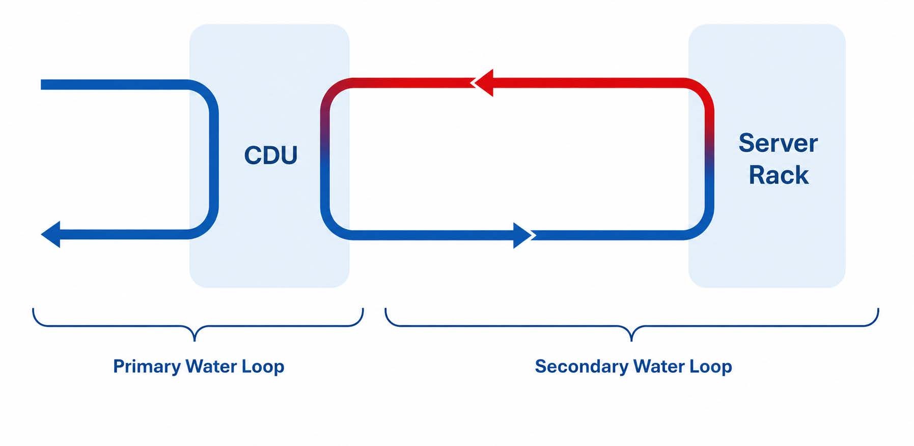
A properly engineered CDU stabilizes loop conditions while isolating facility water from IT or process loops, helping improve uptime, serviceability, and cooling efficiency. As an original equipment manufacturer, CSI engineers, fabricates, installs, and supports CDU systems for data center and industrial cooling applications.
CSI Pump Technology
Pumps provide the motive force to circulate coolant through both the facility and technology loops. CSI performs fluid flow calculations to determine required flow rates, friction losses, pump inlet conditions, and system head requirements before selecting pump and drive packages. Most CDUs employ centrifugal pumps sized to overcome total dynamic head while maintaining target flow across cold plates or heat exchangers. In practice, N+1 pump redundancy (an installed spare) is a proven best practice to preserve uptime through a single failure or during maintenance, while variable-speed drives modulate output under changing loads to minimize energy and pressure transients that can stress components.
Proper CDU pump sizing helps balance performance, capital cost, and operating efficiency. Oversized pumps can increase energy use and upfront cost, while undersized pumps may fail to meet the required cooling performance. CSI models loop hydraulics (including temperature-dependent fluid properties) and tunes control logic to ensure setpoints are held without oscillation or overshoot.
Pump Sizing Factors
| Factor | Why It Matters | Example Consideration |
| Required flow rate | Ensures design heat load is met at target ΔT | IT rack kW, cold plate specs, approach temperature |
| Available head | Overcomes elevation, friction, and device losses | Pipe length/diameter, number of fittings, exchanger plate count |
| Filter pressure drop | Accounts for clean/dirty elements and bypass | Mesh rating, fouling allowance, end-of-life DP for maintenance trigger |
CSI also validates net positive suction head (NPSH) margins, designs for smooth switchover between duty and standby pumps, and integrates drive alarms with facility systems so operators receive early warnings before conditions escalate.
Heat Exchanger Roles and Types in CDU Loops
A heat exchanger transfers heat between two media without mixing them, protecting sensitive IT or process coolant from facility water chemistry while enabling efficient rejection of thermal energy. In CDU systems, heat exchangers are selected based on required heat load, available utility infrastructure, serviceability goals, and pressure drop limits.
Heat Exchanger Type Comparison
| Type | Typical Use | Cooling Capacity | Infrastructure Needs |
| Liquid-to-liquid (plate/frame or brazed plate) | High-density racks; process loads; integration with chilled water | High; tight approach temperatures and high heat flux | Requires dependable chilled water loop, water treatment, isolation valves |
| Liquid-to-air (coil + fans) | Edge sites, labs, or retrofits lacking chilled water | Moderate; limited by air temperature and airflow | Requires sufficient room air path and electrical for fans; less plumbing |
Smaller in-row and in-rack CDUs often use brazed plate exchangers. Larger central CDU systems frequently use serviceable gasketed plate heat exchangers, allowing planned maintenance intervals rather than full unit replacement.
CSI heat exchanger sizing prioritizes required cooling capacity (MW load), realistic approach temperatures, and pressure drop targets—commonly under 10 psi where practical.
Valves and Manifolds for Flow Control
Valves regulate flow and pressure, while manifolds distribute coolant to multiple branches, such as server racks or process tools. In a CDU loop, motorized or proportional control valves trim flow to hold temperature and pressure setpoints and protect components during startup and shutdown. In many CSI designs, control valves regulate the flow of tower or facility cooling media through the heat exchanger to maintain target temperature setpoints. ASHRAE's guidance on water-cooled servers emphasizes controlled flow distribution and ΔT management to protect cold plates and maintain efficiency.
Sensors and Control Systems for Monitoring and Regulation
Temperature transmitters, pressure transmitters, and flow meters provide the real-time data a CDU controller uses to maintain stable operation. The controller continuously computes deviations from setpoints and adjusts pumps and valves to keep operation within defined limits, generating alarms if values drift out of band. Industry guidance notes that closed-loop control is central to a CDU's ability to deliver safe, predictable performance under variable load conditions.
Core control loop, step by step:
- Sensor → measures temperature, pressure, or flow at critical points.
- Controller → compares measurements to setpoints and calculates corrections.
- Actuator → adjusts pump speed or valve position.
- Process feedback → new sensor readings confirm stability or trigger further action.
Redundant instrumentation and failover planning are important in mission-critical CDU environments. CSI's controls integrate with SCADA/BMS for trending, optimization, and remote alerting, with role-based access and maintenance modes that prevent nuisance trips during service.
Expansion Tanks and Filtration Components
“Our 6MW, 10MW and 24MW CDUs are designed so that routine maintenance of filtration, pumps, instrumentation, and other critical components, can be performed without system downtime. CSI’s engineering approach ensures continuous operation during standard service procedures.” - Trent Bullock, Director, CSI Engineering Services
Most CSI CDU systems use properly sized expansion tanks rather than large reservoirs. Expansion tanks accommodate thermal growth and help stabilize loop pressure.
CSI commonly designs for 25-micron full-flow filtration, with optional 1-micron polishing filtration when higher fluid cleanliness is required.
CSI designs for:
- Filter bypass and isolation valves for hot-swap servicing, and DP-based work orders.
- Inclusion of filter-induced DP in the total pump head to preserve setpoint stability over the service cycle.
Need help designing a CDU loop for your facility?
CSI engineers coolant distribution units for data center liquid-cooling applications, including pump sizing, heat exchanger selection, control integration, and skid fabrication. For more information, visit our data center cooling FAQs, or explore our data center components.
Build a More Reliable CDU System
From pump sizing to control integration, CSI engineers design custom liquid-cooling solutions for data center performance.
Explore Data Center CoolingABOUT CSI
Central States Industrial Equipment (CSI) is a leader in distribution of hygienic pipe, valves, fittings, pumps, heat exchangers, and MRO supplies for hygienic industrial processors, with four distribution facilities across the U.S. CSI also provides detail design and execution for hygienic process systems in the food, dairy, beverage, pharmaceutical, biotechnology, and personal care industries. Specializing in process piping, system start-ups, and cleaning systems, CSI leverages technology, intellectual property, and industry expertise to deliver solutions to processing problems. More information can be found at www.csidesigns.com.